ROBOT: Tutorial


HOW  TO MAKE A ANALOG ROBOT ?
We all love watching robot and playing with them. In films Transformers, Terminator top in our list. This article will give you a preliminary knowledge about how to make a robot by yourself . Building a robot is not very troublesome if you stick to the basic of Analog. Problem arises when it comes to wireless, matching the frequency and ability of the antenna to transmit that is quite a tedious job, but here there is no need to care about that .
Lets come to the point , for a perfect functioning of a analog robot , one need constant voltage supply. Variation of voltage or less voltage will give low power to drive the gear motors. So the first thing you need is a SMPS or Switch Mode Power Supply.
A SMPS is an electronic power supply that incorporates a switching regulator in order to be highly efficient in conversion of electrical power. Like other types of power supplies , an SMPS transfers power from a source like electrical power grid to a load while converting voltage and current characteristics. Ideally  , a SMPS  dissipates no power ,in contrast regular power supply regulates the output voltage by constant dissipating power in pass transistor. This power conversion efficiency is a important characteristic of SMPS.   
Here I have used a SMPS of rating 12V/2A.


Other things that I need:-
1.       A Platform.
2.       4 Tires
3.       4 Gear Motors
4.       2 Switch having 6 terminals
5.       Wires
Platform:-


Tire:-

Gear Motor :-
           Here I have used gear motor but we can also use Servo Motor.
 Switch :-
Wires :-


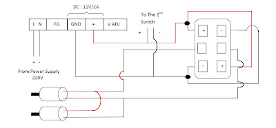
The main connection lies with the SMPS. There are 5 slots in SMPS
    1.       Live (L)
    2.       Neutral (N)                                                      
    3.       FG AC
    4.       DC: 12V/2A
(i)                  GND
(ii)                +
    5.       V ADJ


RF transmitter receiver


The TWS-434 and RWS-434 are extremely small, and are excellent for applications requiring short-range RF remote controls.  The transmitter module is only 1/3 the size of a standard postage stamp, and can easily be placed inside a small plastic enclosure.
TWS-434:  The transmitter output is up to 8mW at 433.92MHz with a range of approximately 400 foot (open area) outdoors.  Indoors, the range is approximately 200 foot, and will go through most walls.....

TWS-434A
The TWS-434 transmitter accepts digital inputs, can operate from 1.5 to 12 Volts-DC, and makes building a miniature hand-held RF transmitter very easy.  The TWS-434 is approximately the size of a standard postage stamp.

TWS-434 Pin Diagram

Sample Transmitter Application Circuit
RWS-434:  The receiver also operates at 433.92MHz, and has a sensitivity of 3uV.  The RWS-434 receiver operates from 4.5 to 5.5 volts-DC, and has both linear and digital outputs.
Click on picture for larger image
RWS-434 Receiver

RWS-434 Pin Diagram
Note: For maximum range, the recommended antenna should be approximately 35cm long.  To convert from centimeters to inches -- multiply by 0.3937.  For 35cm, the length in inches will be approximately 35cm x 0.3937 = 13.7795 inches long.  We tested these modules using a 14", solid, 24 gauge hobby type wire, and reached a range of over 400 foot.  Your results may vary depending on your surroundings.

Sample Receiver Application Circuit
The example above shows the receiver section using the HT-12D decoder IC for a 4-bit RF remote control system.  The transmitter and receiver can also use the Holtek 8-bit HT-640/HT-648L remote control encoder/decoder combination for an 8-bit RF remote control system.  Here are the schematics for an 8-bit RF remote control system:
Click HERE to download the RWS & TWS datasheet in Adobe PDF format.
Driving Relays:
Using the outputs of the HT-12D or HT-648L decoder ICs to drive relays is quite simple.  Here are schematics showing how to drive relays directly from the data-output pins of the decoder.

NPN Relay Driver Circuit

PNP Relay Driver Circuit